|
Rally 200 with Ducati CDI This page describes my effort to replace the original Femsatronic CDI with a standard P model CDI (Ducati) for use in Rally 200. I know this issue has been discussed and explained elseware, but even though my Femsatronic ignition seemed to function I wanted to replace it with something more easily available in case of a malfunction. The original Femsatronic CDI has the spark plug cable molded in the housing, so in case the cable broke at that point it would be impossible to fix. The Ducati CDI seems more sensitive so it starts producing sparks at a lower rpm, which in theory should improve starting. Differences between Femsatronic and Ducati There are no easily available sources for the detailed electronic circuits in the two CDI's. Their function is the same: a diode rectifies the AC voltage from the stator coil to about 200Volts. This charges an internal capacitor and at the time of ignition a silicon controlled rectifier (or Thyristor) conducts in such a way that the capacitor is discharged into the high tension transformer which raised the voltage to more than 10 Kilovolt. The capacitor is charged with the positive cycles only, the negative cycles are not used. But the Femsatronic designer (for some reason) has found it neccesary to load the negative cycles with a 250 ohm resistor. This resistor is positioned in the stator back plate at the same place where you normally find the capacitor for the points ignition. It also has the very same appearence so most people think this is a capacitor. It is NOT. This resistor is not used by the Ducati CDI, therefore the blue wire is not connected in the new setup. A more important difference lies in the trigger circuits for the SCR. These are not well shown or explained anywere, but someone has by experimentation found that the trigger output from the Femsatronic should be loaded with a resistor and a capacitor in order to trigger the Ducati SCR properly. Without these components the ignition becomes erratic or out of timing. My engineering nature forced me to do my own research on this problem. The
following table shows the results of the ignition timing from
various resistances and capacitances.
Specifications call for 24 degrees before tdc Conclusion: 25 - 23 degrees is best, so 1K resistor in parallel with 1µF capacitor. A higher value capacitor might also be used.
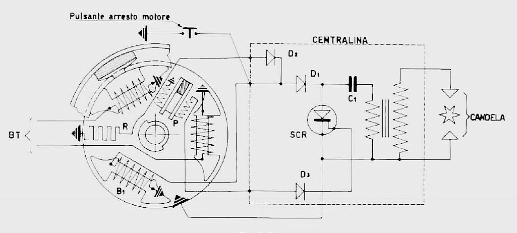
Drawing
shows the Femsatronic diagram. Resistor "R" loads negative
pulses through diode D2, while D1 charges capacitor C1 to 200 volts.
"P" is the coil to trigger SCR through diode D3.
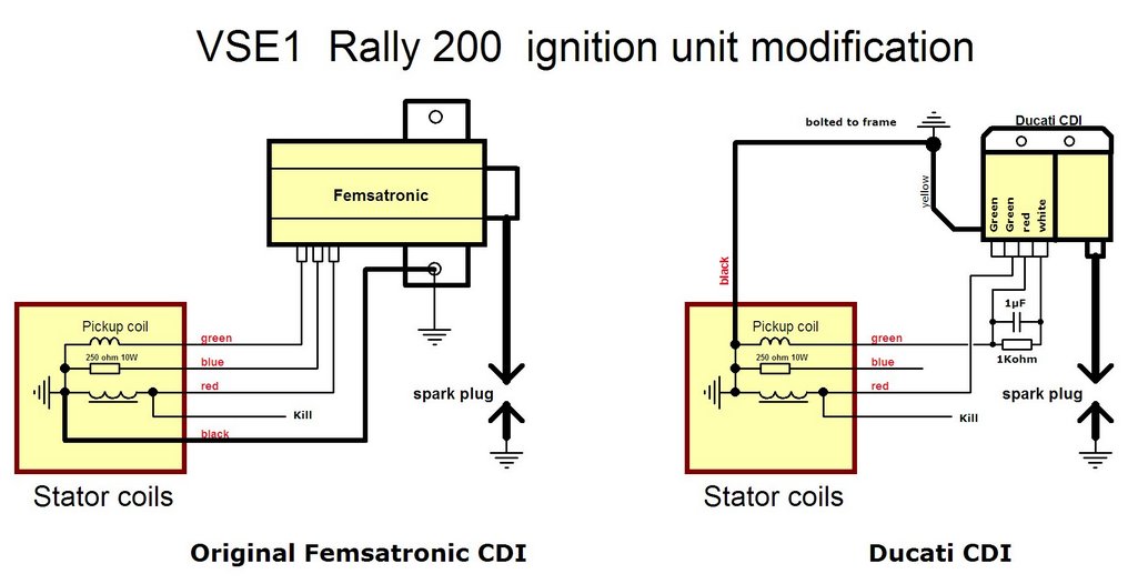
This drawing shows how the stator wires are connected to the Femsatronic and to the Ducati CDI. Note the position of the resistor and capacitor when using the modern type CDI. IMPORTANT: use a ceramic
or foil capacitor not electrolytic or tantalum. This is due to the
nature of pick-up coil output which is both positive and negative
pulses. through hole:
445-2857-ND Note that the blue wire and internal resistor is not used.
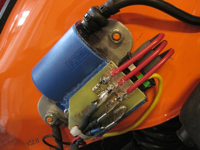
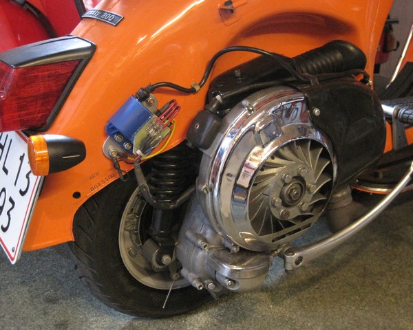
Pictures show the setup on my 1974
Rally 200. A 1Kohm resistor and a 1µF ceramic capacitor is mounted
on a circuit board glued to the Ducati CDI. Jan Haugsted www.vespa-klub.dk
|
||||||||||||||||||||